Choosing the Right Gear

A gear is a mechanical system made up of at least two toothed wheels. Gears are used to transmit a rotary movement with a different torque and speed to that of the driving equipment. The gear wheels mesh with each other and it is the rotation of the wheel driven by the motor that will give movement to the second wheel, through the successive engagement of the teeth, which thus act as levers.

A gear made up of more than two gear wheels is called a gear train. The main function of a gear is to reduce or increase rotational speed and torque. Speed is inversely proportional to torque.

View our gears

  • How do you choose the right gear?

    These are the main criteria to consider when choosing a gear suitable for your intended use:

    • Gear ratio: This will determine whether a given gear can meet your needs.
    • Shaft arrangement: Refers to the relative position of the input and output shafts and determines whether or not to opt for an orthogonal gear solution.
    • Power transmitted by the gear: Determines the choice of tooth type. For example, a gear with spiral teeth can transmit a higher torque than a straight-toothed gear of the same size.
    • Size of the assembly: Certain gear configurations are more compact than others, taking up less space, such as epicyclic gearing.
    • Cost: Gears vary greatly in terms of price and complexity/installation costs, so it’s important to choose the most suitable solution according to your needs and available budget.
  • What are the different types of gears?

    There are different types of gears: spur gears, bevel gears, and worm gears.

    Spur gears

    Spur gears are the simplest and therefore also the most common. The contact line between the teeth is in the same plane as the rotation of the gears.

    Bevel gears

    In these gears, the outer face of the wheel forms an angle to the gear’s axis of rotation. This type of gear is often used to change the angle of the axis of rotation between the drive wheel and the driven wheel.

    Worm gears

    In worm gears, the driving unit is not a wheel, but a worm screw. These gears have a high transmission ratio. The axis of rotation of the worm is perpendicular to the axis of rotation of the crown.

    The special feature of this type of gear is that the rotation is not reversible, i.e. the crown cannot turn the worm, which ensures that the mechanism locks when stationary. As such, this is the type of gear that offers the most security. They are used, for example, in car elevators to prevent the load from moving accidentally.

    NORELEM spur gear

    NORELEM spur gear

    Cross & Morse bevel gear

    Cross & Morse bevel gear

    Framo Morat worm gear

    Framo Morat worm gear

  • What are the different types of gear teeth?

    Gear teeth can be of various types, namely straight, helical, or herringbone.

    Straight-toothed gears

    These are the most common. They have teeth parallel to the axis of rotation. They are fairly easy to manufacture, which explains their use in most mechanical applications. Their main drawback is that they are very noisy.

    Helical-toothed gears

    The helical teeth are oblique to the axis of rotation. In these gears, the number of teeth in contact is constant.
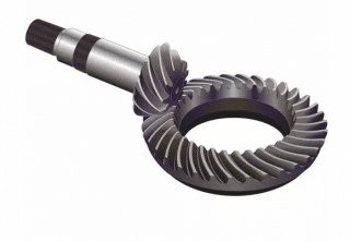
    Helical bevel gears

    Helical bevel gears

    This system has the advantage of generating fewer vibrations and therefore less noise. In addition, as the teeth are arranged diagonally, they have a greater face width than the width of the wheel and can therefore transmit higher forces. However, the manufacture of these gears is much more complex, which makes them more expensive.

    Herringbone-toothed gears

    Herringbone gears are made up of two rows of helical teeth of identical dimensions in a V-shape, i.e. with opposing helices. The double helix has the advantage of canceling out the axial load generated by the inclined teeth. However, like simple helical-toothed gears, they are complex to design and manufacture and therefore cost more than other types of gears. Industries such as the aeronautical industry use herringbone gears.

  • What are the different gear configurations?

    Rack and pinion

    The rack and pinion system makes it possible to transform a rotational movement into a linear movement and vice versa. It consists of a toothed wheel (the pinion) and a toothed straight edge (the rack). As it rotates, the gear wheel pushes on the teeth of the straight edge, which then moves in a rectilinear direction. This type of gear is used in motor vehicles to convert the rotation of the steering wheel into the linear movement of the steering bar to the left and right.

    Parallel or cylindrical gears

    The axes of the gear pair are parallel.

    Bevel gears

    Bevel gears transmit rotation between competing shafts and are therefore used when an angle is required between the gear’s input and output shafts. This solution is used in automotive differentials to obtain a 90º angle between the transmission’s input and output shafts.

    Bevel gears are cone-shaped. When two bevel gears are engaged, their “imaginary” vertices must occupy the same point. Their axes cross at this point, forming an angle, usually 90º, but this can be anywhere between 0º and 180º.

    Reverse gears

    Also known as “torsion gears”, they differ from other gears in that the axes of the gear pair are not in the same plane. This is particularly true of helical left-hand gears or worm gears.

  • Where are gears used?

    Gears are used in most power transmission systems, such as gearboxes, differentials, or in the output of both electric and motor engines. They are found in household appliances as well as in industrial machinery and equipment. They are also found in the gearbox of motor-reducer sets. They are an essential component of most mechanical systems.

RELATED GUIDES
1 Star2 Stars3 Stars4 Stars5 Stars (1 votes, average: 1.00 out of 5)
Loading...
No comment

Leave a Reply

Your email address will not be published. Required fields are marked *