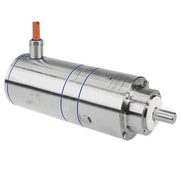
A gear motor is a system that combines a motor and a gear reducer. Gear motors are widely used in various industrial sectors because they allow power to be transmitted through a single device.

A gear motor is a system that combines a motor and a gear reducer. Gear motors are widely used in various industrial sectors because they allow power to be transmitted through a single device.
Gear motors do not require couplings between the motor and the gear reducer. These couplings are often the cause of breakdowns and their assembly can be relatively complicated and time-consuming. The use of gear motors saves time during maintenance operations and improves the Mean Time Between Failures (MTBF).
When choosing a gear motor, you must know the power, torque, and rotational speed required for your application.
Next, you must choose the gear motor configuration. There are different types of gear motors, which are detailed below. The type of shaft used will allow you to choose a gear motor quickly.
The next step will be to choose the type of engine. There are AC gear-motors, DC gear-motors, hydraulic gear-motors, and pneumatic gear-motors. Most gear motors have a speed between 1,200 and 3,600 revolutions per minute (rpm).
As for the gear reducer, the component responsible for changing the speed/torque ratio between the input shaft and the output shaft, there are also several types available. There are gear train gear reducers, planetary gear reducers, worm gear reducers, and bevel gear reducers. Each one has its pros and cons.
In a geared motor, the gear reducer is the element that makes it possible to change the speed/torque ratio between the input shaft and the output shaft of a mechanism. There are several types of gear reducers including gear train gear reducers, planetary gear reducers, worm gear reducers, and bevel gear reducers. Each type of gear reducer has its own specific features, limitations, and advantages.
Gear train gear reducers are a combination of two or more gears. These gear reducers can be purchased at an affordable price, but they cannot handle high torque.
Kollmorgen planetary gear reducer
Planetary gear reducers, also called epicyclic, associate three shafts with different speeds. Planetary gear reducers consist of a central wheel (the sun gear), planet gears, and a ring gear that encircles the others. It generates relatively high torque and transmission power. The input shaft and output shaft are coaxial. The main advantage of these gear reducers is their compact size; they are smaller than conventional gear reducers because the gears rotate around a common shaft. They therefore have a good torque-to-size ratio.
This type of gear reducer is more expensive and requires slightly more complex maintenance, but is nonetheless an excellent choice for systems with little space available and which require high reduction ratios.

Harmonic Drive AG gear motor
Strain wave gear reducers, or harmonic gear reducers, are extremely precise speed reduction systems. They transmit power through a rotating elliptical wave generator, which deforms flexible ring gear, thus inducing the movement of a gear inside it, which is normally fixed. This power transmission enables high-precision angular position in applications requiring a very high transmission ratio (50:1 and above) between input and output.

RENOLD worm gear motor
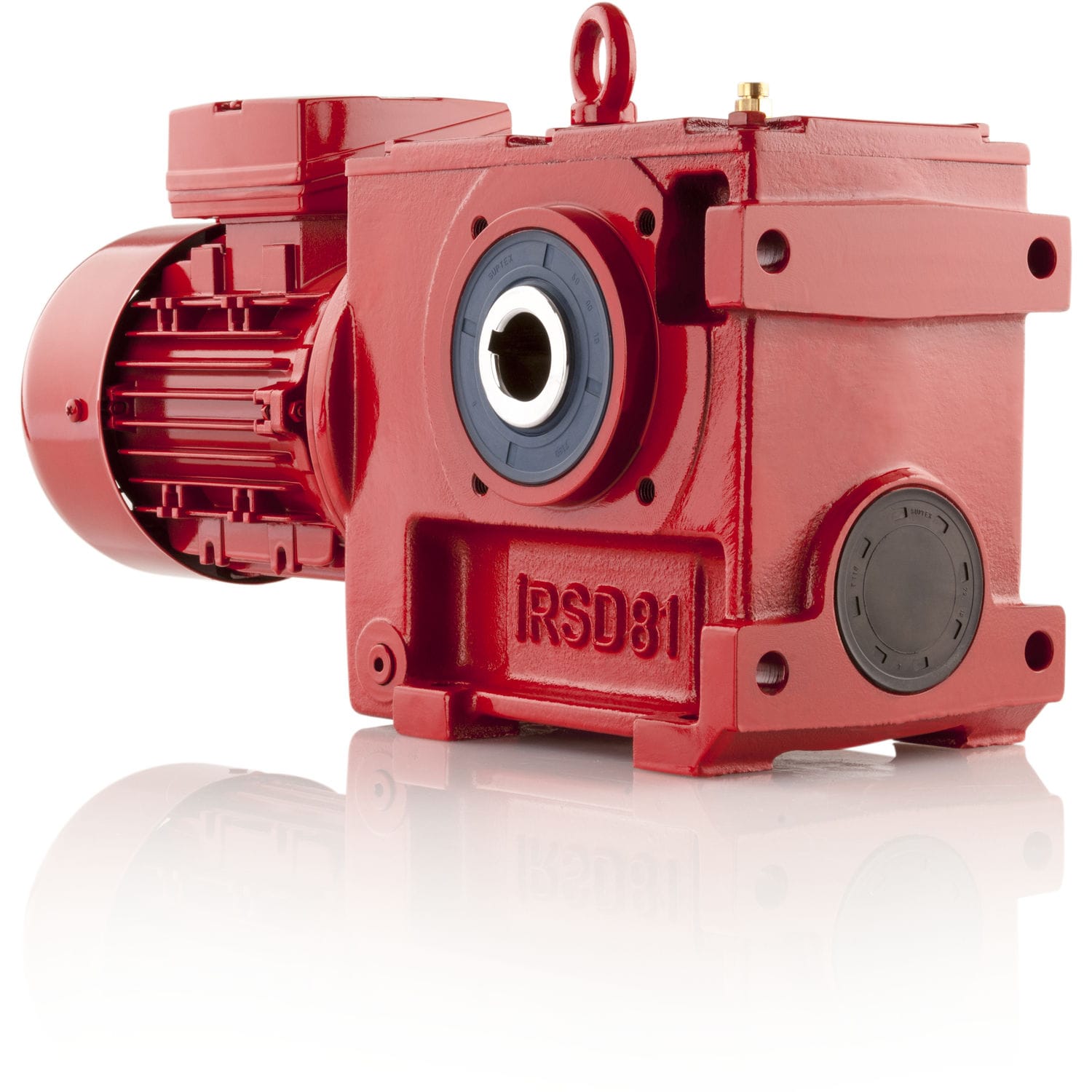
Worm gear reducers consist of a screw and a toothed wheel arranged at right angles to each other. The screw drives the wheel, which is coupled to the output shaft or shafts. This system is often used when a very high transmission ratio is required or when the system needs to be irreversible, as this type of gear reducer only rotates in one direction.
Worm gear reducers have several advantages: compact size, especially for high ratios, low noise level, no vibrations, which results in a good quality drive, high radial load capacity at the output, and good performance/price ratio.
Although their performance depends on the gear ratio and speed, and they heat up more than other technologies, worm gear reducers are increasingly being used in conjunction with other types of gear reducers. Their applications are varied: conveyor systems, handling equipment, winches, slow-speed applications, etc.

NORD bevel gear motor
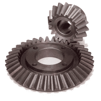
Bevel gear reducers have intersecting shafts, usually perpendicular. They are highly efficient, regardless of the direction of the torque and the input speed. They are more expensive but consume less energy and require little maintenance. These gear reducers can be used universally and have a long service life thanks to the robustness of their teeth, which gives them greater power and resistance to wear. They are mainly used in high-powered conveyor systems, mixers, vehicles, and agricultural machinery.
I-MAK right angle gear-motor
Geared motors can be classified according to the type of shaft.
Parallel-shaft gear-motors have a narrow configuration. However, they cover a torque range from 130 Nm to 18,000 Nm. They are a good choice for tight spaces. They are versatile, allowing for different mounting options, and can therefore be adapted more easily to the space available.
Right angle gear-motors combine efficiency, flexibility, and a compact configuration. For applications requiring high torque, right-angle gear-motors offer above-average performance, combined with a very compact size and great flexibility of use.
Finally, coaxial gear-motors offer significant reduction ratios and a wide range of speeds. They are also compact and can be installed in small spaces.
The choice between a solid shaft and a hollow shaft also adds flexibility to parallel-shaft gear motors.
In gear motor catalogs, manufacturers indicate the specifications of the different motors available. To make the right choice, you should read this information carefully and compare it, particularly the voltage, indicated in volts (V), the power, indicated in watts (W), the rotation speed, indicated in revolutions per minute (rpm), and the torque of the motor, which is measured in Newton meters (N.m).
Your choice of motor must take into account the parameters of the system in which it will be installed: the voltage and power of the mains supply, as well as the torque and rotational speed required by your application.
Terex Cranes conveyor gear motor
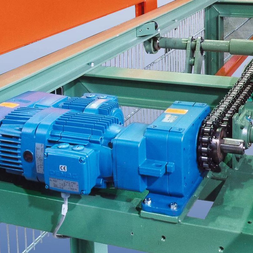
Gear motors have numerous industrial applications. They are used, for example, in conveyor systems, mixers, agitators, pumps, lifting systems, dosing systems, rotary tables, and extruders.

 (1 votes, average: 1.00 out of 5)